Use case for gas conditioning

Benefits of 3S technology in pipeline gas conditioning

Numerical study of three process schemes for Low Temperature Separation

“JT-valve” / “3S-separator” / “2x 3S-separator”

Inlet gas composition:

The calculations of the flow parameters for all three mentioned process schemes – shown and explained below – have been carried out for the gas composition typical of gas condensate fields:

  • Methane [% mol]
  • 88.6
  • Ethane [% mol]
  • 5.1
  • C3+ [g/m3] …
  • 112
  • … of that C5+ [g/m3]
  • 5.1
  • Inlet Pressure [MPa]
  • 11.1

The task: To select the maximum outlet pressure for each process scheme at the dew point temperature minus -20° Celsius for water and hydrocarbons.

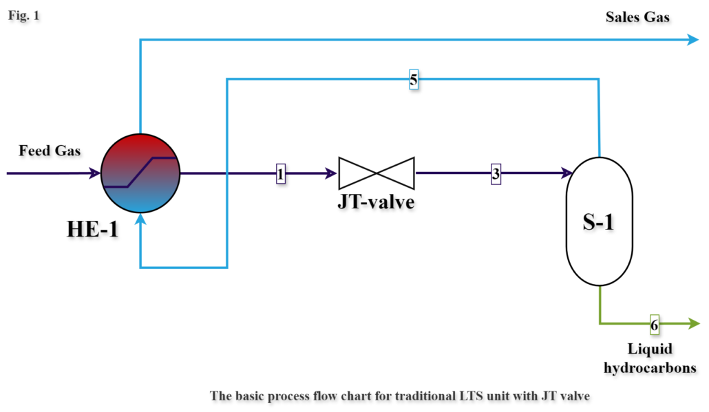
Fig.1

Low temperature separation (LTS) with JT valve
Low temperature separation with JT valve

JT valve

Fig.2

Low temperature separation with one 3S-unit
Fig 2 LTS unit with 3S separator LTS 3S 1

3S-separator

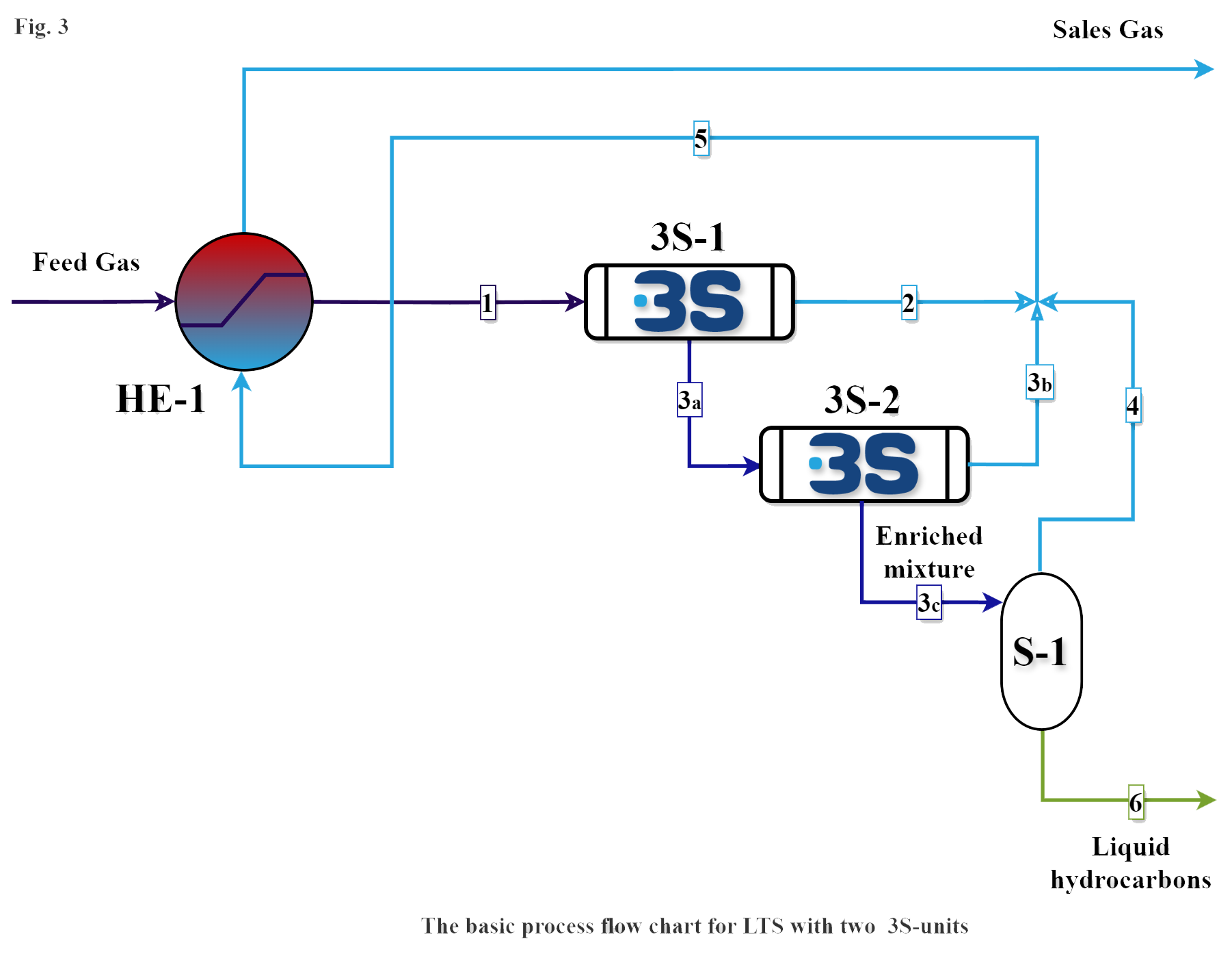
Fig.3

Low temperature separation with two 3S-units
Fig 3 LTS unit with two 3S separators LTS 2 x 3S 2

3S-separator (two units)

Process flow data:

(dew point temperature for water and hydrocarbons is equal to minus -20° Celsius for all three cases)

Process Scheme data 3S separation 3

Benefits of 3S:

cropped 3S Logo 4The analysis of three LTS process schemes demonstrates the benefits of the schemes based on application of 3S in comparison to the scheme with JT valve:

1.     More compact design due to the reduced size of S-1 separator (8 to 25 times), which makes it ideal for offshore application

2.     Provision of required dew point temperature at less pressure drop (10 bar less)

3.     Larger volume of treated sales gas and less volume of flash gas at stabilizer

4.     Application of the process scheme with two (2) 3S separators (Fig.3) allows additional reduction of the separator S-1 volume and ensures an absence of the condensate carry-over due to high level separation of droplets in 3S-2 (Fig.3) , as well as a possibility to use efficient wire-mesh S-1 separator.

Deep explanation & Comparison

Traditional LTS based on JT valve (LTS-JT)

Low temperature separation (LTS) based on JT valve (Fig.1)

Fig 1 LTS unit with JT valve 5

LTS unit with JT (LTS-JT)

  • (Fig. 1.) – Explanation based on simplified process flow chart

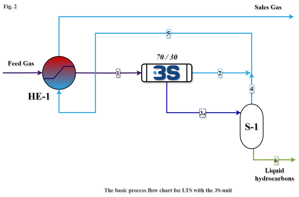
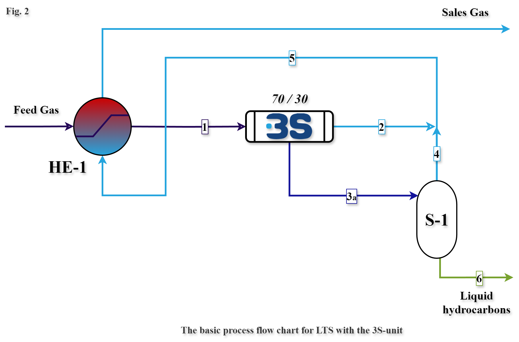
The natural gas flow feeds into the heat exchanger HE-1, whereat the gas is refrigerated by the conditioned outlet gas flow.

The gas flow [1] from the outlet of the heat exchanger is throttled and the gas temperature drops.

The temperature value of the flow [3] is determined by the required dewpoint temperature, which is achieved by the corresponding differential pressure at the JT valve. The obtained liquid phase in the flow [3] is separated from the gas phase in the traditional gas-liquid separator S-1.

The gas flow [5] passes through the heat exchanger HE-1, where it is heated, and then directed into the sales gas pipeline for further transportation.

The unstable liquid flow [6] is directed into the stabilization tower.

LTS unit with 3S-separator (LTS-3S)

Low temperature separation with one 3S-unit (Fig.2)

Fig 2 LTS unit with 3S separator LTS 3S 6

LTS unit with 3S-separator (LTS-3S)

  • (Fig. 2.) – Explanation based on simplified process flow chart

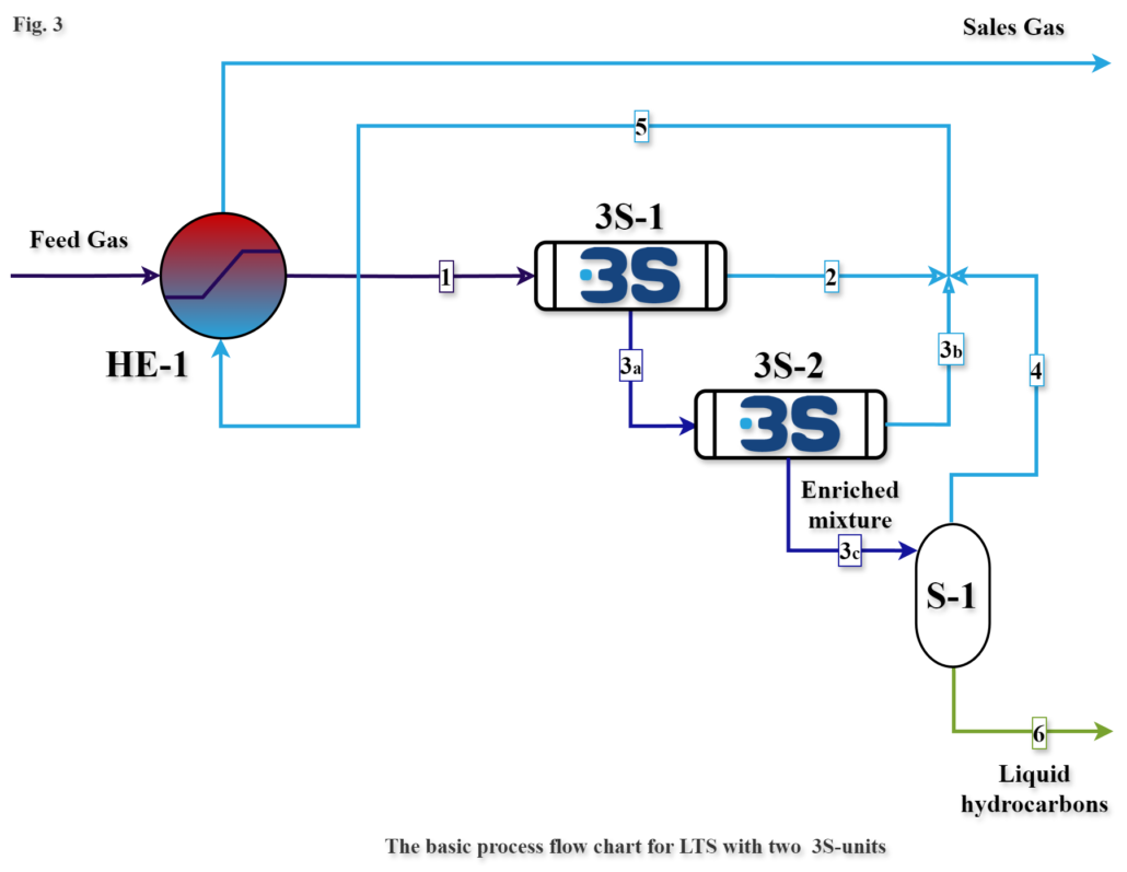
The natural gas flow feeds into the heat exchanger HE-1, whereat the gas is refrigerated by the conditioned outlet gas flow.

The gas flow [1] from the outlet of the heat exchanger is directed to the inlet of the 3S-separator, whereat the flow is swirled and refrigerated in the Laval nozzle, with the subsequent water and condensate droplets formation and coagulation, and further drift of droplets towards the boundary layer and separation into two flows: the purified from water and condensate flow [2] and the enriched with water and condensate flow [3a].

In the traditional LTS projects the most common flow ratio of the flows [2] and [3a] is 70% by 30%. The flow [3a] pressure is slightly higher (0.5 bar) than the pressure of the flow [2], providing further merge of the flows [2] and [4] .

In order to maintain the supersonic mode of the 3S-separator operation the pressure drop has to be above 26% and it’s determined by the requirements to the dew point temperatures.

The liquid phase in the stream [3a] is separated from the gas in the traditional gas-liquid separator S-1. The gas flow [5] passes through the heat exchanger HE-1, where it is heated, and then directed into the sales gas pipeline for further transportation. The unstable liquid flow [6] is directed into the stabilization tower.

It’s important to mention that the capacity of the flow [3a] in the scheme of LTS unit with the 3S-separator – LTS-3S (Fig. 2) is only 30% of the flow [3] in the scheme of the traditional LTS unit (Fig. 1), therefore the size of the traditional gas-liquid separator S-1 will be reduced /8 times reduced size/ in the LTS-3S scheme accordingly.

LTS unit with two 3S-separators (LTS-2x3S)

Low temperature separation with two 3S-units (Fig.3)

Fig 3 LTS unit with two 3S separators LTS 2 x 3S 7

LTS unit with two 3S-separators (LTS – 2 x 3S)

  • (Fig. 3.) – Explanation based on simplified process flow chart

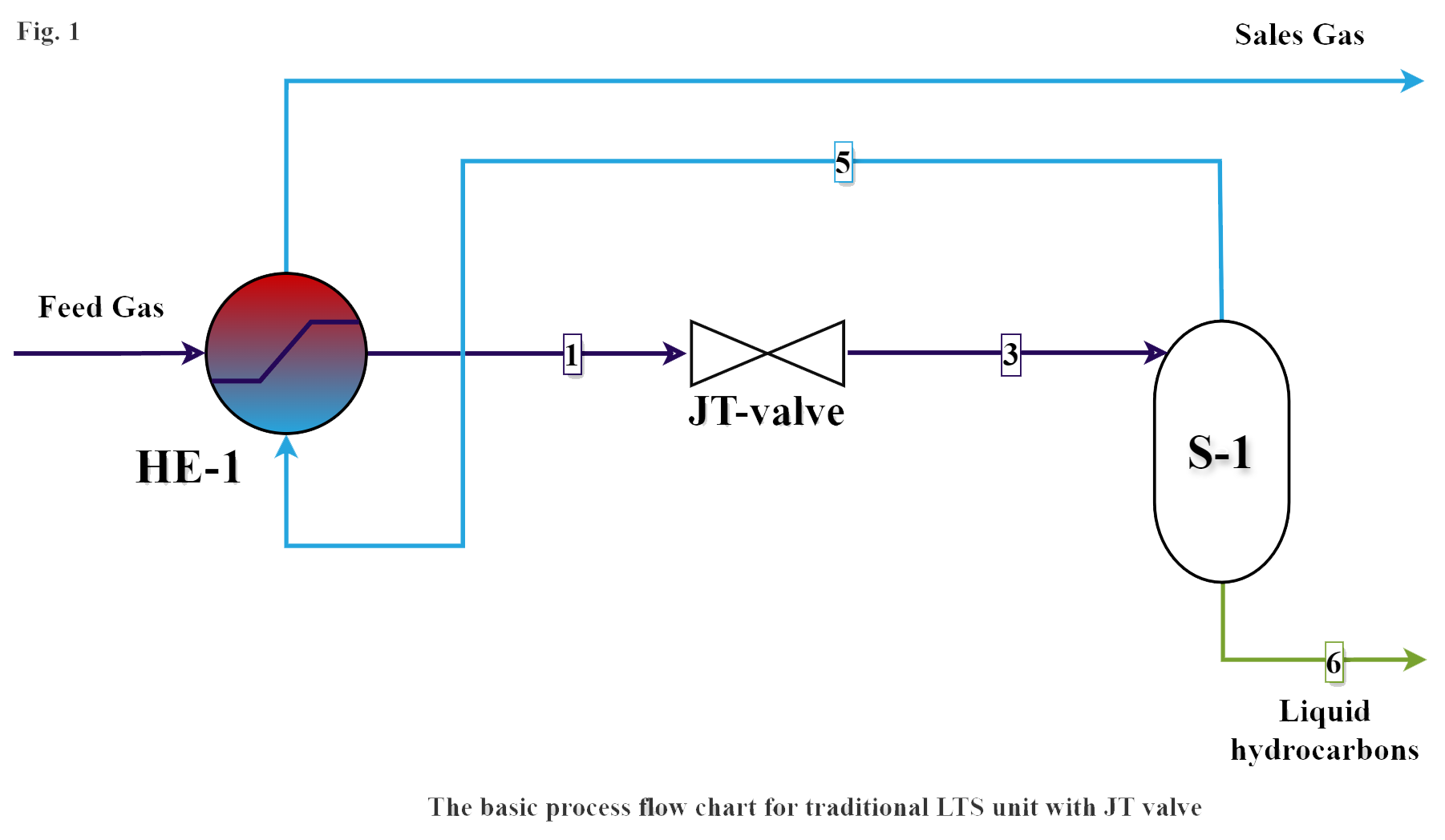
The natural gas flow feeds into the heat exchanger HE-1, whereat the gas is refrigerated by the conditioned outlet gas flow. The gas flow [1] from the outlet of the heat exchanger is directed to the inlet of the 3S-separator (3S-1), whereat the flow is swirled and refrigerated in the Laval nozzle, with the subsequent water and condensate droplets formation and coagulation, and further drift of the droplets towards the boundary layer and separation into two flows: the purified from water and condensate flow [2] and the enriched with water and condensate flow [3a].

In the traditional LTS projects the most common flow ratio of flows [2] and [3a] is 70% by 30%. In order to maintain the supersonic mode of the 3S-separator operation the pressure drop has to be above 26% and it’s determined by the requirements to the dew point temperatures.

The flow [3a] enters into the special 3S-separator (3S-2), which operates in subsonic mode with a minimum pressure drop (approximately 0.5 bar). High quality separation of the flow [3a] takes place in this 3S-separator where it splits into gas-liquids flow [3c] (with small gas content) and pure gas flow [3b].

The ratio of the flows [3b] and [3c] is 80% by 20%.  The liquid phase in the flow [3c] is separated from the gas in the traditional gas-liquid separator S-1.

The gas flow[5] passes through the heat exchanger HE-1, where it is heated, and then directed into the sales gas pipeline for further transportation. The unstable liquid flow [6] is directed into the stabilization column.

It’s important to mention that the capacity of flow [3c] in the scheme of LTS – 2 x 3S unit (Fig. 3) is only 6% of the flow [3] in the scheme of traditional LTS unit (Fig. 1), therefore the size of the traditional gas-liquid separator S-1 will be reduced /25 times reduced size/ in LTS-3S scheme accordingly.

The process scheme of LTS unit with two 3S-separaotrs (LTS– 2 x 3S) provides significant reduction of a gas plant equipment size and weight and an undisputable benefits which are specifically important in the offshore applications.