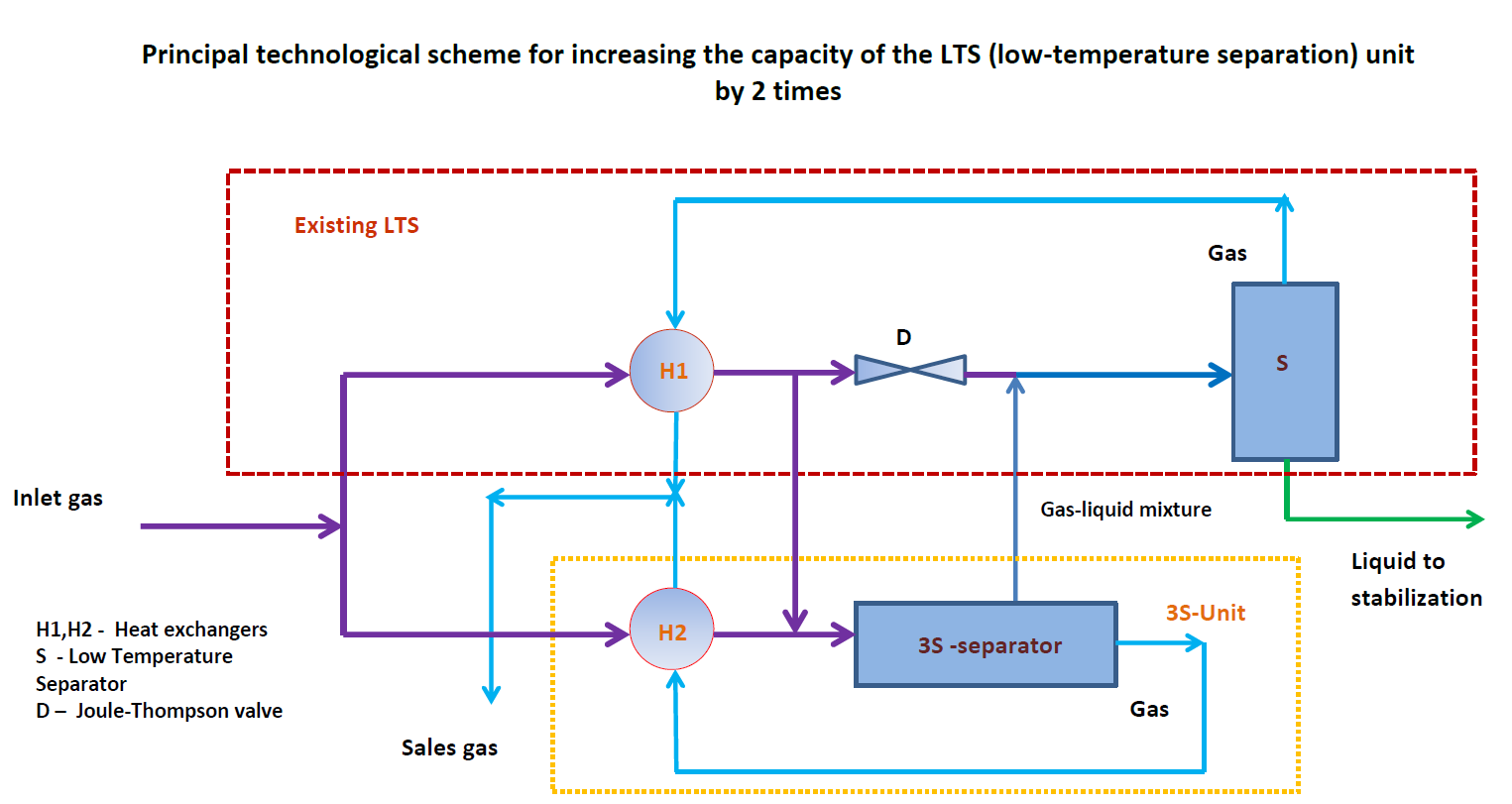
Natural gas processing, gas separation, removes impurities and separates hydrocarbons to produce pipeline-quality gas, recovering byproducts like ethane, propane, and butane.

3S Separator Technology: A Breakthrough in Supersonic Gas Separation


Overview of the 3S Separator

The 3S Separator (SuperSonic Separation) is a revolutionary technology for natural gas and process gas treatment, offering an innovative, highly efficient, and compact solution for gas-liquid and gas-solid separation. Built upon the principle of supersonic expansion, the 3S Separator utilizes advanced fluid dynamics to create extreme thermodynamic conditions, achieving condensation and separation in a single, continuous, and energy-efficient process.

The 3S system offers a new paradigm in gas conditioning, dehydration, and hydrocarbon dew point control, enabling significant operational and economic advantages over conventional technologies such as Joule-Thomson (JT) valves, glycol dehydration, and mechanical separation.


How It Works: The Supersonic Separation Principle

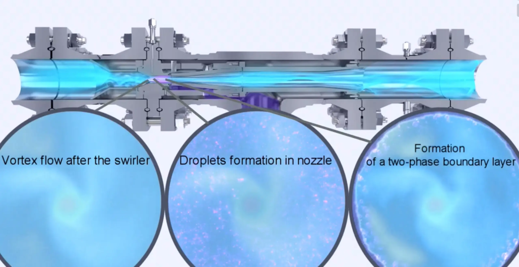
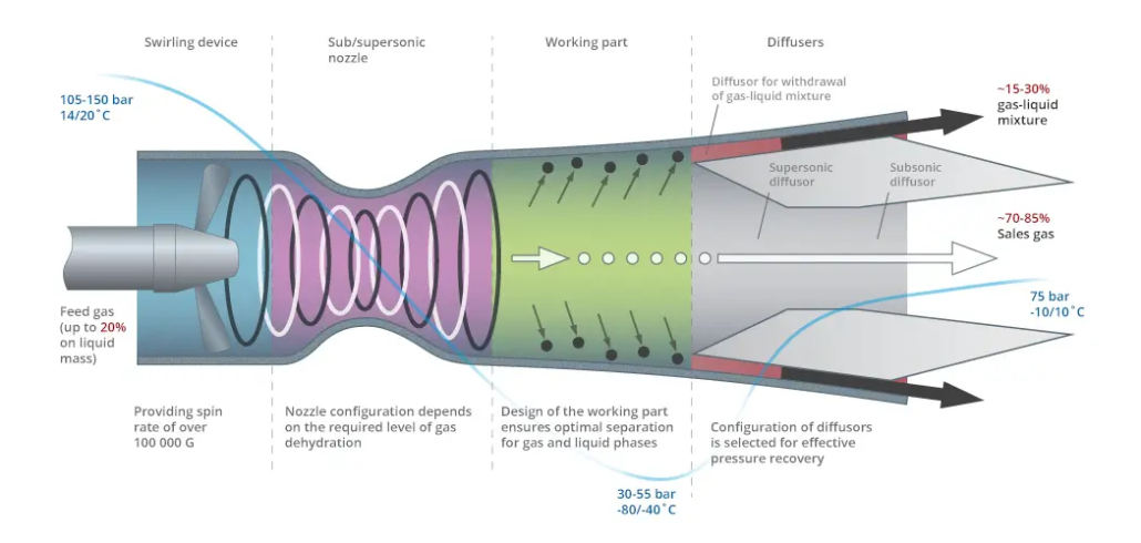
3S separator - working principle
3S Separator Technology: A Breakthrough in Supersonic Gas Separation 4

The 3S Separator operates through a multi-step process:

  1. Acceleration and Expansion: The gas enters a Laval nozzle where it is accelerated to supersonic speeds. This expansion causes a rapid drop in temperature and pressure.
  2. Condensation: Due to the extreme cooling, heavier hydrocarbons, water, and other condensable components form droplets.
  3. Swirling and Separation: A swirl element imparts a high centrifugal force, driving droplets and solid particles to the walls, separating them from the gas stream.
  4. Recompression and Recovery: The lean gas is recompressed, and the separated liquids and solids are extracted downstream.

This sequence occurs in a matter of milliseconds, without moving parts, resulting in highly reliable and low-maintenance operation.

🔗More => 3S separator operating principle


Key Features of the 3S Separator

FeatureDescription
No Moving PartsEnsures high reliability and minimal maintenance.
Compact DesignUp to 70% smaller and lighter than traditional systems.
Energy EfficientUtilizes pressure drop instead of external power for operation.
Modular and ScalableEasily integrated into various system sizes and configurations.
Instantaneous ResponseSeparation occurs in milliseconds, enabling real-time process adjustments.

Typical Applications

Common Uses

  • Natural Gas Processing
  • Pipeline Gas Conditioning
  • Hydrocarbon Dew Point Control
  • Gas Dehydration
  • CO2 and H2S Removal (with upstream cooling and sorbents)
  • NGL (Natural Gas Liquids) Recovery

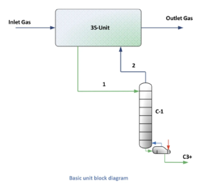
Process Flow Example – 3S Separator

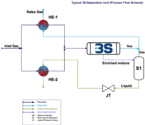
The following schematic outlines a typical 3S Separation Unit:

Typical 3S-Separation Unit (Process Flow Scheme)
  1. Feed gas is pre-cooled (if needed).
  2. The gas passes through the Laval nozzle and swirling chamber.
  3. Condensates are removed via a cyclonic separation zone.
  4. Clean, dry, and conditioned gas exits the system.

This layout can be adapted for upstream, midstream, and downstream operations depending on the customer’s process requirements.

🔗More => Standard Process Flow Scheme 3S separator


Benefits of the 3S Technology

BenefitImpact
Enhanced Gas QualityDelivers pipeline-spec or sales-grade gas without additional treatment.
Lower Operational CostsNo chemical reagents, heaters, or compressors needed downstream.
Increased Liquid RecoveryHigh efficiency in NGL and condensate separation.
Environmental ComplianceReduced emissions and zero venting possible.
Fast ROILower CAPEX and OPEX with short payback periods.
Minimal FootprintIdeal for offshore platforms, FPSOs, and remote installations.

Comparing Technologies

Technology Comparison

TechnologyLogo 3S gas teh 1
3S Separator
JT ValveGlycol DehydrationMechanical Separator
Moving PartsNoNoYesYes
FootprintSmallMediumLargeMedium
Energy RequirementLowMediumHighMedium
Separation EfficiencyHighMediumHigh (dehydration)Low
Liquid RecoveryHighMediumLowLow
Environmental ImpactLowMediumHigh (chemicals)Medium

Why Choose 3S Technology?

The 3S Separator is a proven and field-tested solution designed for modern energy systems. Whether your goal is to maximize liquid recovery, meet pipeline specs, reduce operating costs, or increase process efficiency, the 3S system provides a powerful alternative to legacy technologies.

With multiple units successfully operating in harsh environments and across diverse applications, the 3S solution is ready to meet the challenges of the evolving energy landscape.

More => 3S separator & 3S technology projects world wide


Contact and Integration Support

3S offers comprehensive engineering support, from feasibility studies to full integration into existing or new gas processing systems.

To learn more about how the 3S Separator can enhance your operations, contact our team or visit:

For more information on how the 3S Separator can improve your operations, get in touch with our team or visit:

🔗 www.3s-most.eu
🔗3S Separator – Inquiry Form


Typical 3S-Separation Unit (Process Flow Scheme)
Standard Process Flow Scheme for 3S-Separation Units

The inlet gas is divided into two streams: one is cooled at the [HE-1] Heat Exchanger, and the other at the [HE-2] Heat Exchanger.

To achieve efficient liquid extraction in the [3S-separator], the inlet gas is chilled to approximately minus –70°C to minus –90°C.

The cooled gas streams are combined and sent to the [3S-separator], where they are split into two outputs: a treated gas stream and a rich gas-liquid stream (comprising 15-30% of the inlet gas volume). This rich stream is directed to the [S1] low-temperature separator.

Gas from the [S1] separator is mixed with treated gas from the [3S-separator] and sent to [HE-1], where it is reheated by the cooling inlet gas. This results in the final NGL plant sales gas, primarily consisting of methane with a small amount of ethane.

The unstable liquid from [S1] is throttled and sent to [HE-2], where it cools part of the inlet gas by partially evaporating (acting as an evaporator).

After passing through [HE-2], the rich gas-liquid mixture, or “ethane-enriched condensate,” is processed in a conventional low-temperature separation (LTS) unit.

Key benefits of this process include efficient heat recovery, enhanced liquid extraction, and optimized gas processing with minimal energy consumption.

The Need for Inlet Air Cooling in Gas Turbine Power Plants in Hot and Humid Environments, and the Application of 3S Separators

Gas turbine power plants are widely used for electricity generation due to their efficiency and reliability. However, they are highly sensitive to ambient conditions, particularly temperature and humidity. In hot and humid environments, gas turbines face significant operational challenges, especially because hot air is less dense, reducing the power output and increasing the compressor work required. This leads to a decrease in efficiency, especially when ambient temperatures exceed 40°C. (The effects are particularly pronounced in hot regions, where ambient temperatures can exceed 40°C, leading to power output reductions of up to 30%.) Therefore, cooling the air before it enters the turbine’s compressor is critical for improving performance in these conditions.

Challenges in Hot and Humid Environments

  1. High Temperatures: In hot climates, such as deserts or tropical regions, the reduced air density decreases oxygen content for combustion, leading to reduced turbine output and increased energy consumption by the compressor. Power output can drop by up to 30% in these conditions.
  2. Humidity: In tropical regions or areas with high humidity, the presence of water vapor reduces combustion efficiency, as the water vapor displaces oxygen in the air.

Traditional Inlet Air Cooling Solutions

Several cooling methods are commonly used to address these challenges:

  1. Evaporative Cooling: Cools the inlet air by evaporating water, which works well in dry climates but is less effective in humid environments.
  2. Chiller Systems: Use mechanical refrigeration to cool the air but are energy-intensive and costly.
  3. Fogging Systems: Spray water droplets into the intake air, cooling it as the water evaporates. This method is cost-effective but less efficient in very humid conditions.
  4. Thermal Energy Storage (TES): Uses chilled water or ice stored during off-peak hours to cool the air during peak demand, but requires significant infrastructure investment.

The 3S Separator as a Cooling Solution

An innovative and highly efficient approach to cooling inlet air for gas turbines is the 3S (Supersonic Swirling Separator) technology. Originally developed for the oil and gas sector to separate gas mixtures, the 3S separator operates by accelerating gases through a convergent-divergent Laval nozzle, causing rapid cooling and condensation of gas-phase components. The cooling effect generated by this process makes it an ideal candidate for use in gas turbine inlet air cooling.

Application of 3S Separators for Inlet Air Cooling

In this application, the 3S separator can be integrated into a cooling system that uses free energy from various sources to power a refrigeration cycle. The proposed system utilizes hot flue gases from the turbine exhaust to generate the required cooling for the turbine’s inlet air.

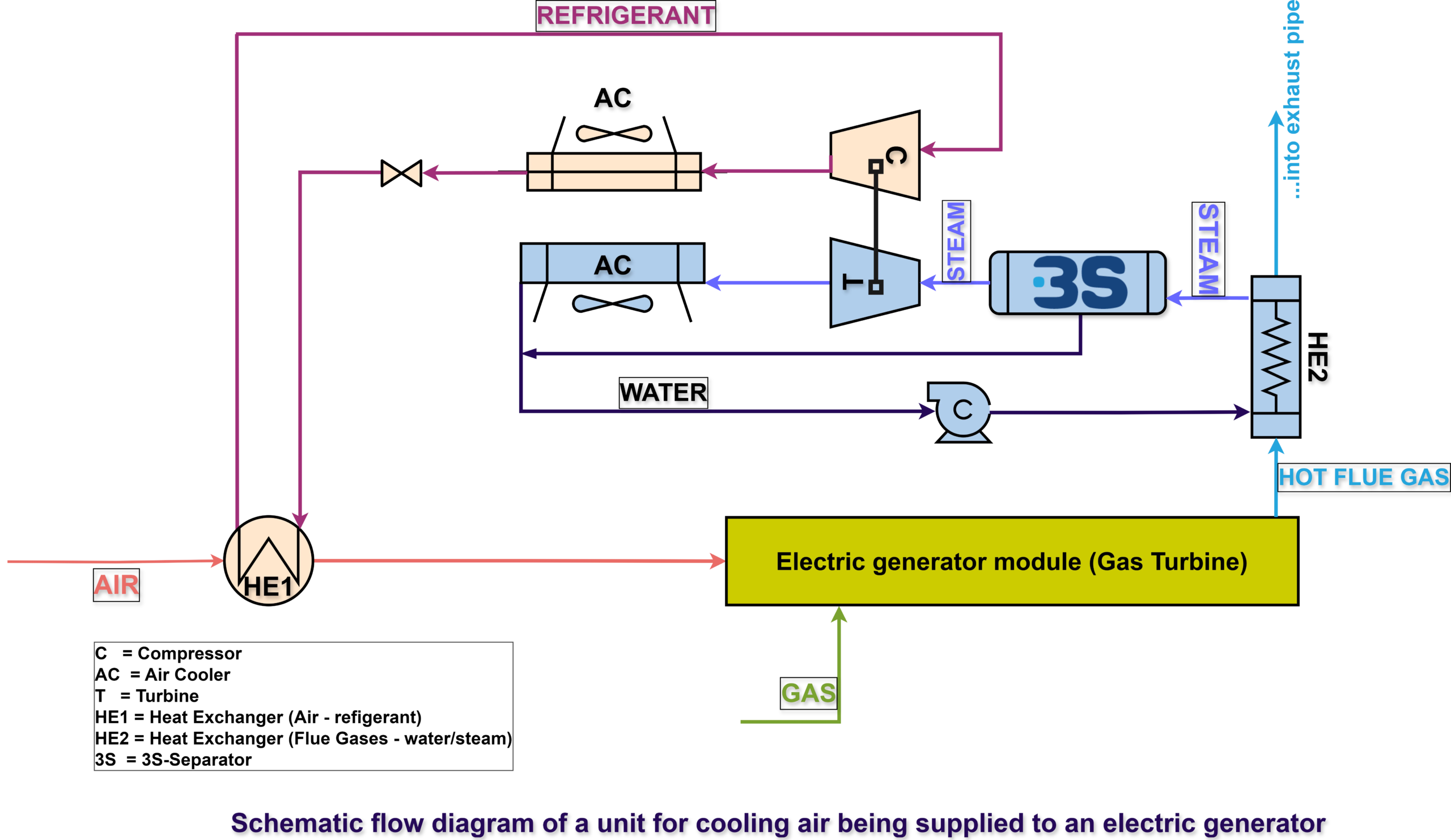
Inlet Air Cooling for Gas Turbine using 3S-Separator

Proposed 3S Separator-Based Cooling System Using Hot Flue Gases

The system operates as follows:

  1. Heat Exchanger (HE2): Hot flue gases from the gas turbine heat water in a heat exchanger. The pressurized water is then transformed into a vapor-liquid mixture.
  2. 3S Separator: The vapor-liquid mixture enters the 3S separator, where the liquid phase is separated from the vapor. The supersonic swirling flow enhances the separation, allowing the vapor fraction to power a turbine connected to a compressor.
  3. Turbine (T) and Compressor (C): The turbine, driven by the vapor from the 3S separator, powers the compressor, which operates a refrigeration cycle (closed circuit) using a refrigerant such as freon or propane.
  4. Heat Exchanger (HE1): In this heat exchanger, the cooled refrigerant absorbs heat from the inlet air, reducing its temperature before it enters the gas turbine’s compressor.
  5. Water Recirculation: The separated water is recirculated to the pump (if applicable), ensuring continuous operation.

This configuration takes advantage of the waste heat generated by the turbine itself, thus reducing the need for external energy inputs and enhancing the overall efficiency of the cooling process.

Alternative Source: Free Energy from Pressure Drop in Gas Distribution Pipelines

Apart from utilizing the waste heat from hot flue gases, the 3S separator can also harness free energy from pressure drops in nearby gas distribution pipelines. In many cases, natural gas pipelines experience significant pressure reductions as gas is transported to lower-pressure distribution networks. This energy can be recovered and used to power the refrigeration system for cooling the gas turbine’s inlet air.

Advantages of 3S Separator-Based Cooling Systems

  1. Energy Efficiency: By using waste heat from flue gases or free energy from pressure drops, the 3S separator significantly reduces the need for external energy inputs, improving the overall energy efficiency of the cooling process.
  2. Environmentally Friendly: The system leverages renewable energy sources (waste heat or pipeline pressure drops), reducing the carbon footprint of the gas turbine plant.
  3. Cost-Effectiveness: The 3S separator-based system eliminates the need for large, energy-intensive chillers, offering a compact and cost-efficient solution.
  4. Flexibility: The system can be adapted to various refrigerants and environmental conditions, making it suitable for a wide range of climates and regulatory requirements.

Local Specificities for Application

  • Desert and Arid Regions (e.g., Middle East, North Africa): In areas with high ambient temperatures, the 3S separator system can utilize the excess heat from flue gases to cool the turbine inlet air. The system’s ability to operate efficiently in high temperatures makes it ideal for these regions.
  • Tropical and Humid Regions (e.g., Southeast Asia, Brazil): In hot and humid environments, the 3S separator can cool and dehumidify the air before it enters the turbine, improving performance in conditions where both temperature and humidity negatively impact gas turbine efficiency.
  • Regions with Developed Gas Infrastructure (e.g., U.S., Europe): Where high-pressure gas distribution pipelines are available, the 3S separator can harness the free energy from pressure drops in the pipelines, providing an additional energy-efficient cooling option.

Conclusion

The 3S separator presents an innovative solution for cooling gas turbine inlet air in hot and humid environments. By utilizing free energy from either hot flue gases or pressure drops in nearby gas pipelines, the system offers a flexible, energy-efficient, and cost-effective alternative to traditional cooling methods. As gas turbines continue to play a critical role in global power generation, especially in regions with extreme temperatures, the adoption of 3S technology for inlet air cooling can help ensure more reliable and efficient power generation.

In the world of natural gas processing, technologies such as Joule-Thomson (JT) valves and turbo-expanders have long been employed to reduce the temperature of gases, separate gas components, and recover valuable by-products. These systems, though effective, often come with trade-offs between efficiency, complexity, and cost. However, the advent of Supersonic Separators, such as the 3S-Separator, represents a transformative step in gas processing, merging the simplicity of JT valves with the efficiency of turbo-expanders to offer a highly effective and energy-efficient solution for gas separation.

This article explores how supersonic separators combine the core functionalities of JT valves and turbo-expanders, explains their technical properties, and highlights their advantages in various gas processing applications.

Joule-Thomson (JT) Valves: Simple, but Limited

JT valves operate on the principle of the Joule-Thomson effect, which describes the temperature change in a gas as it expands through a valve without exchanging heat with its surroundings. In a gas processing plant, JT valves are typically used for:

  1. Pressure Reduction: Gas pressure is reduced by allowing it to expand through the valve.
  2. Temperature Drop: Due to the Joule-Thomson effect, the temperature of the gas decreases during the expansion.
  3. Condensation: This cooling effect helps in condensing heavier hydrocarbons, such as natural gas liquids (NGL), enabling their separation from the gas stream.

Advantages of JT Valves:

  • Simplicity: The JT valve is a passive device with no moving parts, making it easy to maintain and operate.
  • Cost-Effective: JT valves are relatively inexpensive compared to more complex systems.
  • Low Energy Requirements: The process is passive and doesn’t require additional energy input.

Limitations of JT Valves:

  • Limited Efficiency: The cooling efficiency is relatively low, and the process can result in suboptimal recovery of hydrocarbons.
  • Pressure Dependency: JT valves require a significant pressure differential to induce meaningful cooling.
  • Fixed Output: The degree of cooling cannot be easily controlled or optimized.

Turbo-Expanders: Efficient, but Complex

Turbo-expanders operate by expanding high-pressure gas through a turbine, which generates mechanical energy as the gas does work on the turbine blades. The mechanical energy can be used to drive compressors or generate electricity, and the gas exiting the expander experiences a significant temperature drop, making it ideal for gas separation.

Key Functionalities of Turbo-Expanders:

  1. Pressure Reduction: Like JT valves, turbo-expanders reduce the pressure of the gas.
  2. Efficient Cooling: Turbo-expanders achieve a much greater temperature drop than JT valves, leading to enhanced separation of NGLs and other components.
  3. Energy Recovery: The mechanical energy produced by the turbine can be harnessed for other processes, improving overall energy efficiency.

Advantages of Turbo-Expanders:

  • High Efficiency: Turbo-expanders provide significantly better cooling and separation efficiency than JT valves.
  • Energy Recovery: The ability to convert mechanical energy into usable power or drive compressors makes turbo-expanders energy efficient.
  • Precision Control: Turbo-expanders allow for more precise control over the cooling process.

Limitations of Turbo-Expanders:

  • Complexity: Turbo-expanders are complex mechanical systems with moving parts, making them more prone to wear and requiring higher maintenance.
  • Higher Costs: The initial investment and operational costs are higher due to the complexity of the system.
  • Energy Requirements: While turbo-expanders recover energy, they often require higher energy inputs than simpler systems like JT valves.

Supersonic Separators: The Best of Both Worlds

Supersonic separators, such as the 3S-Separator, combine the simplicity of JT valves with the high efficiency of turbo-expanders. These separators work by forcing gas into a supersonic flow regime, creating a pressure drop and rapid cooling effect that facilitates gas separation. The process mimics key properties of both JT valves and turbo-expanders but offers unique advantages that improve overall gas processing performance.

Super Sonic Separations - key Advantages
Supersonic Separators: Merging the Best of Joule-Thomson Valves and Turbo-Expanders 8

Core Functionalities of Supersonic Separators:

  1. Supersonic Flow and Cooling: Gas is accelerated to supersonic speeds in a Laval nozzle (a converging-diverging nozzle), causing an adiabatic expansion that results in a significant pressure drop and a rapid cooling effect. This mirrors the cooling efficiency of turbo-expanders but with a much simpler design.
  2. Gas-Liquid Separation: The rapid cooling causes heavier hydrocarbons (such as NGLs) and water vapor to condense into liquid form, which can then be separated from the gas stream.
  3. Cyclonic Action: After the supersonic expansion, the gas undergoes a cyclonic effect, which separates the liquid and solid particles from the gas due to centrifugal forces. This separation is more efficient than the conventional gravity-based separation seen in JT systems.
  4. No Moving Parts: Like JT valves, supersonic separators have no moving parts, making them robust, reliable, and low-maintenance.
  5. Energy Efficiency: Supersonic separators operate passively, requiring little to no external energy input, while achieving comparable cooling and separation results to turbo-expanders.

Properties and Characteristics of Supersonic Separators:

  • Pressure Reduction and Cooling: Similar to both JT valves and turbo-expanders, supersonic separators achieve a large pressure drop and rapid cooling. However, they do this more efficiently by leveraging supersonic flows rather than relying solely on expansion through a valve or turbine.
  • High Efficiency: The efficiency of separation in supersonic separators rivals that of turbo-expanders, particularly in recovering NGLs and other valuable by-products.
  • Compact and Simple Design: While turbo-expanders are large and complex, supersonic separators offer a compact, simple design that is easier to install and operate.
  • Cost-Effective: The simplicity of the design reduces both CAPEX and OPEX. Maintenance costs are lower due to the absence of moving parts, and the initial cost is generally less than a full turbo-expander system.
  • Energy Recovery Potential: While supersonic separators don’t generate mechanical energy like turbo-expanders, the energy efficiency gained through their passive operation offsets this, making them an ideal choice for energy-conscious operations.

Supersonic Separators in Application: Key Benefits

NGL Recovery:

In gas plants, supersonic separators are particularly valuable for NGL recovery, as they achieve high levels of liquid extraction without the complexity of turbo-expanders. The supersonic expansion leads to a sharp temperature drop, causing heavy hydrocarbons to condense and separate from the gas stream efficiently.

CO2 and Water Removal:

Supersonic separators are also used for CO2 and water vapor removal, addressing challenges in gas fields with high CO2 content. The rapid cooling provided by the supersonic flow causes CO2 to condense and be removed as a liquid, significantly reducing its concentration in the gas stream.

Dew Point Control:

For pipeline transportation, dew point control is critical to avoid condensation issues. Supersonic separators offer a reliable solution by achieving effective gas cooling, ensuring that heavier hydrocarbons are removed and the gas remains in a stable phase during transit.

Conclusion

Supersonic separators like the 3S-Separator offer a revolutionary combination of the simplicity of JT valves and the efficiency of turbo-expanders, without the downsides of complexity or high energy consumption. By utilizing supersonic flow dynamics, these separators achieve rapid pressure drop and cooling, enabling efficient gas separation with minimal operational costs. Their compact, energy-efficient design makes them an ideal solution for a variety of applications in natural gas processing, from NGL recovery to CO2 removal and dew point control. This technology represents a significant leap forward in gas processing, offering a reliable and cost-effective alternative to traditional systems.

Supersonic separation technology has emerged as a highly efficient and innovative solution for natural gas processing, offering several advantages over conventional methods. This cutting-edge technology is rooted in the principles of gas dynamics and thermodynamics, which leverage the behavior of gases at supersonic speeds. By rapidly cooling gas flows through convergent-divergent nozzles, separating condensed droplets, and using cyclonic forces, this method presents numerous benefits for the energy industry. This article will explore the key advantages of supersonic gas separation, focusing on its applications in natural gas dehydration, heavy hydrocarbon extraction, and offshore processing.

diagram of a liquid fluid flow
Supersonic Separator

1. Efficiency in Gas Dehydration

One of the primary applications of supersonic separators is the dehydration of natural gas. Natural gas typically contains water vapor, which can lead to the formation of hydrates or contribute to corrosion in pipelines. Traditional dehydration methods such as absorption, adsorption, and membrane separation, though effective, come with challenges including high operational costs, energy consumption, and complex setups.

Supersonic separation technology, on the other hand, offers a highly efficient alternative. In this process, gas is cooled rapidly in a supersonic nozzle, causing water vapor to condense into droplets. These droplets are then separated using centrifugal forces in a swirling flow, leaving behind dry gas. This method requires no chemical additives or external energy inputs for heating, making it significantly more energy-efficient. It also minimizes the risk of hydrate formation, as the gas resides in the supersonic separator for only a few milliseconds, reducing the need for hydrate inhibitors like ethylene glycol.

2. Compact and Lightweight Design

One of the most significant benefits of supersonic separators is their compact and lightweight design. Traditional gas processing equipment, such as glycol dehydration units or refrigeration systems, tend to be bulky, require extensive space, and come with a high energy footprint. In contrast, supersonic separators integrate several stages of gas processing into a single, compact unit. This makes the technology particularly suited for offshore and subsea installations, where space and weight constraints are critical.

The compact design of supersonic separators not only reduces the overall equipment footprint but also lowers capital and installation costs. For offshore applications, where deck space is a premium, supersonic separators offer a streamlined solution, reducing both the complexity of the installation process and the operational costs associated with maintenance and energy consumption.

3. No Moving Parts – Minimal Maintenance

Unlike traditional gas separation equipment, supersonic separators operate without any moving parts. This design feature greatly enhances the reliability and longevity of the system. Traditional equipment such as compressors, turbines, and expanders require regular maintenance and are prone to wear and tear due to their mechanical components. In contrast, supersonic separators rely purely on the physics of high-speed gas flow, which significantly reduces the need for routine maintenance.

This “no moving parts” design is particularly advantageous for remote or offshore installations where maintenance operations can be logistically challenging and costly. Operators can rely on the consistent performance of supersonic separators without the need for frequent human intervention, thereby improving the overall cost-effectiveness of the technology.

4. Cost Savings in Operation and Maintenance – SuperSonic Separator

Supersonic separators offer substantial cost savings, both in terms of operational expenses and capital investment. Traditional methods of natural gas dehydration and heavy hydrocarbon extraction require large, energy-intensive equipment, complex systems, and significant human intervention. Supersonic separators, due to their simplicity and compact design, offer lower initial capital costs. Additionally, the absence of chemicals like ethylene glycol, coupled with minimal energy requirements for cooling and separation, further reduces the overall operational costs.

One of the notable advantages of supersonic separators is their ability to conserve reservoir energy. By effectively cooling the gas and recovering pressure in the diffuser section, these separators optimize the energy use of the gas stream, ensuring that more energy is retained within the gas for downstream processing or transportation. This translates to long-term energy savings, particularly in applications such as offshore gas processing, where energy efficiency is crucial for maintaining economic viability.

5. Superior Performance in Heavy Hydrocarbon Extraction

Supersonic separators excel at separating heavier hydrocarbons (C3+, C5+) from natural gas. These components can condense out of the gas stream under the supersonic cooling effect within the nozzle. Unlike traditional methods that rely on complex cooling and separation processes involving multiple stages and chemical additives, supersonic separators use rapid cooling and centrifugal forces to achieve high separation efficiency in a single stage.

Experimental data have demonstrated that supersonic separators can achieve superior performance in hydrocarbon recovery compared to conventional methods such as Joule-Thomson (JT) valves or turboexpanders. For instance, under certain conditions, the recovery of heavier hydrocarbons using supersonic separators can be 10-20% more efficient than with JT valves. This enhanced performance makes the technology particularly valuable for gas processing facilities aiming to maximize liquid hydrocarbon extraction, such as in liquefied petroleum gas (LPG) production.

6. Environmentally Friendly Operation

In addition to cost and performance benefits, supersonic separators offer a more environmentally friendly alternative to traditional gas processing methods. Many conventional gas dehydration and separation technologies rely on chemical additives or energy-intensive processes, which can result in higher greenhouse gas emissions or the release of hazardous chemicals into the environment.

Supersonic separators operate in a closed, chemical-free system. The absence of chemicals such as glycol or methanol reduces the risk of environmental contamination. Furthermore, the compact and energy-efficient design of the system contributes to lower overall emissions, aligning with the industry’s increasing focus on sustainability and reducing carbon footprints.

7. Versatility in Applications

The versatility of supersonic separators makes them suitable for a wide range of applications in the natural gas industry. They can be used for gas dehydration, heavy hydrocarbon extraction, and CO2 removal, as well as in the production of liquefied natural gas (LNG). Their ability to operate under both high and low pressures further extends their usability across different processing environments.

Additionally, supersonic separators are highly adaptable to both onshore and offshore installations. Their compact design, ease of automation, and minimal maintenance requirements make them ideal for challenging environments such as offshore platforms and subsea installations, where traditional gas processing equipment may be impractical or too costly.

Conclusion

Supersonic separation technology represents a major leap forward in the efficiency, cost-effectiveness, and environmental sustainability of natural gas processing. With its ability to deliver superior dehydration and hydrocarbon separation performance in a compact, reliable package, this technology is poised to become a key tool in the future of natural gas treatment. Its versatility and low maintenance make it particularly suitable for offshore and remote installations, where traditional equipment may falter. As the energy industry continues to prioritize sustainability and cost savings, supersonic separators are likely to see increasing adoption across a range of applications.

References:
– Article: Supersonic separation technology for natural gas dehydration in liquefied natural gas plants; by: Jiang Bian and Xuewen Cao:
– Article: SuperSonic Gas Technologies; by: Jiang Bian and Xuewen Cao:Vladimir Feygin, Salavat Imayev, Vadim Alfyorov, Lev Bagirov, Leonard Dmitriev, John Lacey, TransLang Technologies Ltd., Calgary, Canada

Supersonic separation technology is an innovative method employed in natural gas processing for separating water, heavy hydrocarbons, and other impurities. This method, driven by supersonic flow through a Laval nozzle, offers several advantages over traditional techniques such as absorption, adsorption, and membrane separation. The attached review provides a detailed exploration of the supersonic separation mechanism, its structure, and its application in various sectors of the natural gas industry.

The Supersonic Separation Process

In natural gas processing, separating impurities like water and heavy hydrocarbons is crucial for ensuring pipeline quality and maintaining the gas’s heating value. Traditional methods like absorption, which involves bulk phase materials such as triethylene glycol, and adsorption, which uses materials like silica gel, can be complex and require high investments. These methods can also result in significant energy losses during transportation.

Supersonic separation, however, offers a streamlined alternative. The process involves natural gas passing through a Laval nozzle, where it accelerates to supersonic speeds. The rapid expansion of the gas results in a drop in temperature, leading to the condensation of water vapor and heavy hydrocarbons. The resulting droplets are then separated from the gas flow using a cyclone separator.

This technique has several advantages. The short residence time within the separator prevents the formation of hydrates, which eliminates the need for inhibitors and regeneration systems. Moreover, the device is static, containing no rotating parts, thus enhancing reliability and making it suitable for unmanned operations, particularly on offshore platforms.

Structural Overview of the Supersonic Separator

Supersonic separators generally consist of a Laval nozzle, a cyclone, and a diffuser. There are two primary designs:

  1. Cyclone Back-Placed Separator : In this design, the cyclone is positioned after the Laval nozzle. The flow is relatively uniform, with no significant shock waves, allowing for efficient separation when the shock wave is controlled.
  2. Cyclone Front-Placed Separator (3S-Separator): In this design, the cyclone is placed at the entrance of the Laval nozzle. This setup ensures the swirling and condensation of gas occur simultaneously, leading to enhanced separation efficiency and less droplet re-evaporation.

The design of the Laval nozzle is crucial in ensuring efficient gas expansion and condensation. Common design methods for the nozzle include the Witozinsky curve and the Bicubic parametric curve, which ensure uniform and stable airflow.

Theoretical Framework

The supersonic separation process is based on the principles of spontaneous condensation, a non-equilibrium phase change that occurs when the gas expands in the Laval nozzle. The process can be divided into two stages:

  1. Nucleation: As the gas expands, it becomes supersaturated, forming condensation nuclei. The droplet growth occurs on these nuclei as they continue to absorb vapor molecules from the surrounding gas.
  2. Droplet Growth: The growth of droplets is governed by heat and mass transfer processes. The vapor molecules condense on the nuclei’s surface, releasing latent heat, and the droplets continue to grow. This process occurs at a microscopic scale, with droplet diameters typically in the nanometer range.

Various models have been developed to simulate the nucleation and growth of droplets in supersonic flows. These include the Classical Nucleation Theory (CNT) and its modified versions, such as the Internally Consistent Classical Nucleation Theory (ICCT). These models, although effective, often lack accuracy, especially in accounting for the effects of real gas behavior and droplet radius.

Research and Simulation

One key challenge in supersonic separation is the occurrence of shock waves, which can disrupt the separation process by causing droplet re-evaporation. Researchers have explored various design modifications to mitigate this issue, such as adjusting the nozzle’s expansion angle and lengthening the expanding section to maintain a stable separation environment.

Experimental studies complement these simulations. For example, light scattering, small-angle x-ray scattering (SAXS), and tunable diode laser absorption spectrometry are used to measure the condensation parameters in supersonic flows. These experiments provide valuable data for validating numerical models.

Applications in Natural Gas Processing

Supersonic separation technology has proven its effectiveness in natural gas processing, particularly in dehydration and heavy hydrocarbon removal. Field tests and industrial applications have demonstrated its potential to replace traditional methods in certain scenarios.

For instance, in the past decade field tests have been conducted, where supersonic separators were used to process natural gas under high-pressure conditions, achieving significant reductions in water and heavy hydrocarbon content.

There is also also a lot of successfully delivered 3S Technology Projects worldwide where the 3S-separtors have been installed solving the various problems in the of gas.

New Applications

The versatility of supersonic separation technology has led to its application in other areas of natural gas treatment, including:

  1. Natural Gas Liquefaction: By cooling and liquefying natural gas at supersonic speeds, this technology has the potential to improve the efficiency of liquefied natural gas (LNG) production. Researchers have proposed double-stage liquefaction processes using supersonic separators to enhance liquefaction rates.
  2. Removal of Acid Gases: Supersonic separators are also being explored for removing acid gases like carbon dioxide and hydrogen sulfide from natural gas. The process relies on the condensation of these gases at low temperatures and high pressures, followed by separation from the main gas flow.
  3. Syngas Purification: In theoretical models, supersonic separation has been proposed for the purification of syngas by removing water vapor, carbon dioxide, and other impurities.

Future Research Directions

While supersonic separation technology has shown promise, there are several areas for further research:

  1. Modeling and Simulation: Current nucleation models need refinement, particularly in accounting for droplet radius and real gas effects. More accurate models would improve the prediction of condensation rates and droplet growth.
  2. Experimental Validation: More accurate experimental techniques are needed to measure droplet parameters, such as size and distribution, under supersonic conditions. This would enable better validation of numerical models.
  3. Multiphase Flow Studies: The interaction between different condensable components in gas mixtures, as well as the effects of impurities on condensation, requires further investigation. Advanced mathematical models that account for these interactions are essential.
  4. Droplet Dynamics: The behavior of droplets in supersonic flows, including their collision and coalescence, needs to be studied in greater detail. Understanding these processes will lead to more efficient separator designs.

In conclusion, supersonic separation technology represents a significant advancement in natural gas processing, offering a compact, efficient, and environmentally friendly alternative to traditional methods. With continued research and development, its applications will likely expand, further transforming the natural gas industry.